PANPs

Archive for discussions from 2010. Please post new discussions in the appropriate forum.

Moderators: neps, Matthew, Michael Pajaro

Locked
StevenMillar
Volunteer
Posts: 5
Joined: Tue Sep 07, 2010 5:28 pm
antispam: No
What year did the original Knight Rider start: 1982

PANPs

Post by StevenMillar » Tue Sep 07, 2010 5:54 pm

Hi guys,

New member here looking for advice,

I have a latching unit and 4 momentary pushbuttons that I want to make into a PANP unit,

I have this unit about 2 years but am only getting around to setting it up functionally now but cant get it to work,

I have tried every possible `hookup` and not even a flicker when going through the latching board, I know the bulbs are working so its something to do with the wiring sequence going through the board.

Ive attached two pics and tried to label the 2nd one with A,B,C,D etc where the terminals are so if anyone has any info or advice it might make it easier to discuss.

Appreciate all or any advice on this as played around with it for few days and not a blink when trying the board.

Thanks

Image
Image

User avatar
taoworm2323
FLAG Assistant
Posts: 958
Joined: Tue Aug 19, 2008 12:47 am

Re: PANPs

Post by taoworm2323 » Wed Sep 08, 2010 1:55 am

Your gonna want to e-mail Christian Forget. He's the one that made the boards.
He is VERY nice and friendly and will guide you though any installation questions you might have. :good:
"Don't tell me what I can't do!" ---John Locke

StevenMillar
Volunteer
Posts: 5
Joined: Tue Sep 07, 2010 5:28 pm
antispam: No
What year did the original Knight Rider start: 1982

Re: PANPs

Post by StevenMillar » Wed Sep 08, 2010 9:44 am

Hi Taoworm thanks for the reply,

Yeah it was Christian I got most of my stuff from and he great, we exchanged a few mails back and forth alright but I still couldnt get it to work :oops:

It was just a thought that maybe some of the replica builders here might have been able to say connect A to whatever etc.

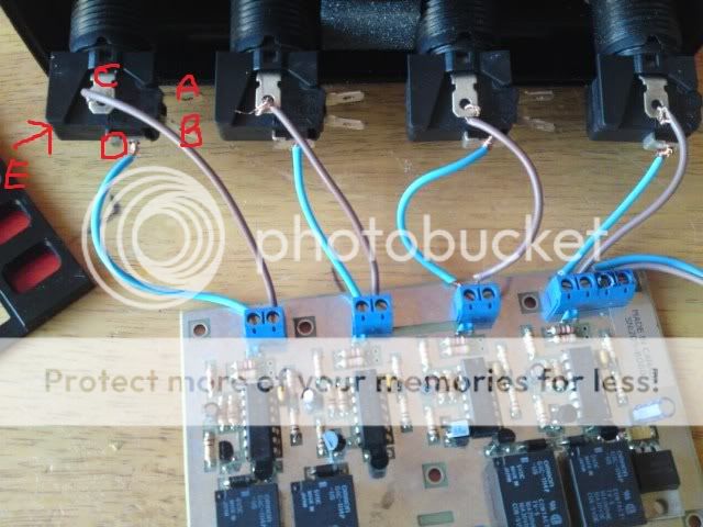
Below is the first set of instructions I got but to be honest cant work out what goes where :?


Latching interface (K205)

Note: following instructions are in reference to the PANP buttons but the latching interface can as well be used with any momentary push button.

The PANP push buttons are momentary. If you want a switch to hold the contact after touching it, you need the interface board. The interface board is simply an array of 4 separate, identical latching circuits. You use one, two, three or all four depending on what you want to do with the push buttons.

Connect +12V and GND to the interface board to supply power to it.

The PP, AA, NN and PP indications are only a reference, you do not have to follow any specific order. My suggestion is to associate PP to Power, AA to Auto, NN to Normal and the second PP to Pursuit. To use the interface, the momentary push buttons connect to the PP or AA or NN or PP again. The momentary contact will be applied to that side. If this is not clear enough, connect the terminal identified C (for Common) to the first P and connect the NO (Normally Open) terminal of the same switch to the second P.

On the other side of the interface board you have P A N P terminals. These are the 4 outputs which will be turned on and off when a momentary push button switch is connected to the other side.

Locked